¶ Slotted Rail Terminal (SRT)
¶ Summary
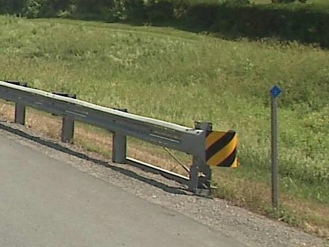
The SRT is a proprietary gating terminal. [1] The design is currently owned and maintained by Trinity Highway Products LLC. It was originally designed by the Texas Transportation Institute (Texas A&M), to comply with the NCHRP 230 (National Cooperative Highway Research Project) standard.
From the manufacture's website:
The Slotted Rail Terminal (SRT-350®) is a gating, flared end terminal and is available in a 6-Post and 8-Post system. The SRT-350® HBA® 6-Post system, has 2 steel breakaway posts, 4 wood CRT posts, and is assembled in a straight-line flare.
¶ Testing
| Test | Status | Level | Version |
|---|---|---|---|
| NCHRP-350 | ✔️ | TL-3 | |
| MASH | ❌ |
¶ Operation
Because of it's design the SRT can only be used on a level site where there is a large clear and traversable area behind the terminal.
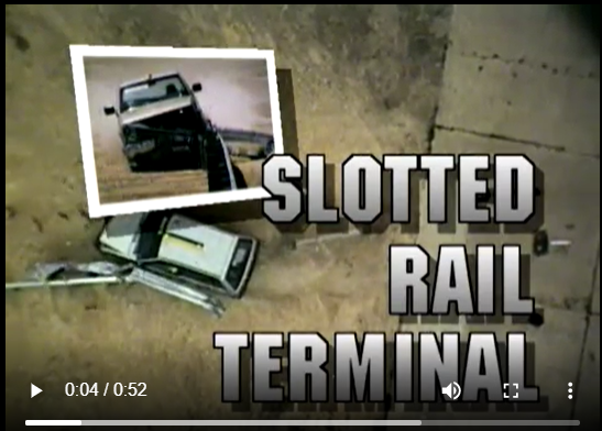
This video, though older, describes the operation of the SRT well. It was sourced from Youtube and is for internal reference only.
Heads up, the video has sound 🔊.
¶ Common Issues
- Rail attached to incorrect posts
- Rail backwards - slots guards on the upstream end of upstream terminal or downstream end of downstream terminal
- Incorrect second rail section - usually has no slots
- Bearing plate fallen off of post 1 or twisted
- Cable loose
¶ Versions
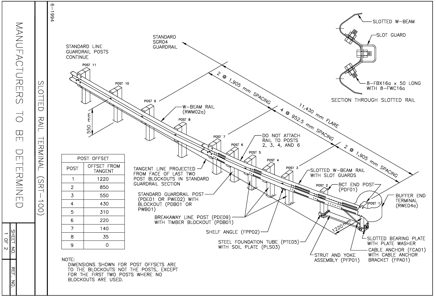
¶ SRT_350_01 - Parabolic, wooden, 27" high with 10 posts
This was the first SRT approved under 350. approved by the FHWA in 1995 in letter cc-31.
(Click on photo to view to pdf of drawing)
Features include:
- Head
- A wrap around head, BCT style, with the free end nearly touching the post
- Rail
- A 3.81m (12.5') slotted w-beam spanning posts 1 - 3
- Two 685mm (27") long slots
- Slots fall between post 1 - 2 and post 2 - 3
- A 7.62m (25') slotted w-beam spanning posts 3 - 11
- Two 300mm (12") slots, 1.9m (6.25') apart
- Slots fall between posts 4 - 5 and posts 6 - 7
- A 3.81m (12.5') slotted w-beam spanning posts 1 - 3
- Posts
- 2 wooden breakaway posts in steel foundation tubes as posts 1 and 2
- 8 wooden, CRT posts as posts 3 - 10
- Approved for both steel and wood line posts
- Parts
- A rectangular folded steel slotguard with 8 holes
- W-beam backup plates (12" sections of W beam) on posts 2, and posts 4 - 10
- A rectangular slotted bearing plate - open end goes up
- Two ground struts or a single 3"x3"xl/4" angle ground strut between post 1 and 2 as approved in letter cc-124
- Post spacing
- Posts 1 - 2 and 2 - 3 spaced 75" apart
- Posts 3 - 11 spaced 37.5" apart
- Post 11 is the first line post
- Flare
- A parabolic curve over posts 1 - 9 totaling 11.4m long with 1.2m offset
- Rail placement and attachments
- Post 1, 5 and 11 are connected to the rail
- Posts 2 - 4 and posts 6 - 10 are not connected to the rail
- The top of the W beam at 27.63" (550mm)
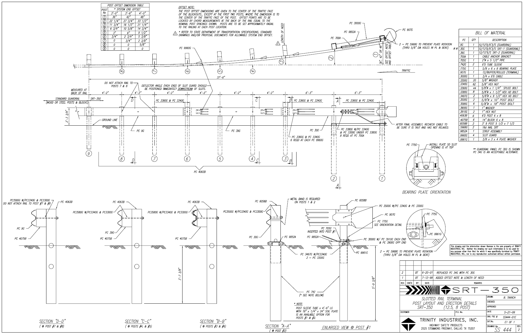
¶ SRT_350_02 - Parabolic, wooden, 27" high with 8 posts
This was approved by the FHWA in 1998 in letter cc-51 further modified i 1999 in letter cc-51a. This
followed an initial rejection of design changes in letter cc-31a in 1998. It's manual is provided by Trinity
Highway, described as the SRT 8 Post System.
(Click on photo to view to pdf of drawing)
- Head
- A shorter spoon head (7.5"), forming roughly a U-shape at the end of the post
- Posts
- 2 wooden breakaway posts in steel foundation tubes as posts 1 and 2
- Approved with the following tubes: 1.82-m or 1.98-m long steel tubes without soil plates, and 1.52-m or 1.37-m long steel tubes with soil plates
- 8 wooden, CRT posts as posts 3 - 10
- Approved for both steel and wood line posts
- 2 wooden breakaway posts in steel foundation tubes as posts 1 and 2
- Rail
- A 3.81m (12.5') slotted w-beam spanning posts 1 - 3
- Two 685mm (27") long slots
- Slots fall between post 1 - 2 and post 2 - 3
- A 3.81m (12.5') slotted w-beam spanning posts 3 - 6. Two options for slots were approved.
- Three 300mm (12") slots, 1.27m (50") apart, or two 300mm (12") slots, 2.655m (104.5") apart
- Slots fall between all three posts, or between posts 4 - 5 and posts 6 - 7
- A 3.81m (12.5') unslotted w-beam spanning posts 6 - 9
- A 3.81m (12.5') slotted w-beam spanning posts 1 - 3
- Parts
- A trapezoidal folded steel slotguard with 6 holes
- No backplates
- A rectangular slotted bearing plate - open end goes up
- Post spacing
- Posts 1 - 3 are spaced 75" apart
- Posts 3 - 8 are spaced 50" in posts 3 - 8
- This reduces the number of posts in the system to 8. Post 9 is the first part of the normal w-beam
- Flare
- A shorter parabolic flare of 8.9m (29.2' long)
- Options for either a 0.9m, 1.07m or 1.22m offset
- Rail placement and attachment
- Posts 1 - 6 and post 9 are connected to the rail
- Posts 7 and 8 are not connected to the rail
- A steel strap must be applied under the bolt holes on post 1 and 2 when the 1.07m offset or the 1.22m offset are used
- The top of the W beam at 27.63" (550mm)
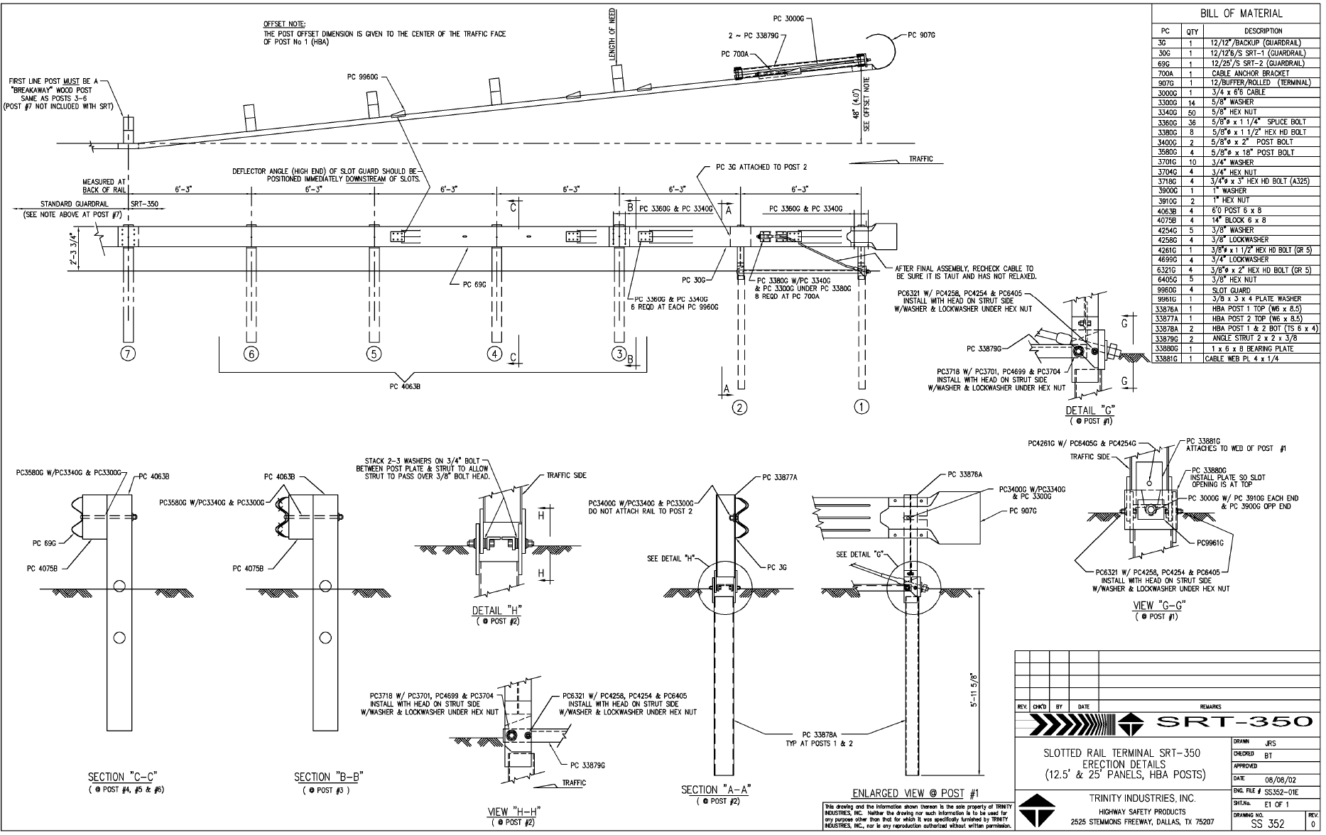
¶ SRT_350_03 - Linear, wooden, 27" high with 7 posts
This is the first linear (straight) flare SRT terminal. It was approved in 2000 in letter cc-72. It's manual is supplied by Trinity Highway Industries, and the pdf is here.
(Click on photo to view to pdf of drawing)
Features include:
- Head
- A shorter spoon head (7.5"), forming roughly a U-shape at the end of the post
- Same head as the previous SRT
- Posts
- 2 steel hinged breakaway (HBA) posts in steel foundation tubes as posts 1 and 2
- 5 wooden, CRT posts as posts 3 - 7 (post 7 is a regular line post in the drawings but only a CRT on 7 is approved in the letter)
- Approved for both steel and wood line posts
- Rail
- A 3.81m (12.5') slotted w-beam spanning posts 1 - 3
- Two 685mm (27") long slots
- Slots fall between post 1 - 2 and post 2 - 3
- A 3.81m (12.5') slotted w-beam spanning posts 3 - 5
- Two 300mm (12") slots, 2.655m (104.5") apart
- Slots fall between posts 3 - 4 and posts 4 - 5
- A 3.81m (12.5') unslotted w-beam spanning posts 6 - 9
- A 3.81m (12.5') slotted w-beam spanning posts 1 - 3
- Parts
- A trapezoidal folded steel slotguard with 6 bolts
- No backplates
- A rectangular slotted bearing plate - open end goes up
- Two ground struts or a single 3"x3"xl/4" angle ground strut between post 1 and 2 as approved in letter cc-124
- Post spacing
- Posts 1 - 7 spaced 6'3" (75") apart
- Post 8 is the first line post
- Flare
- A linear flare 11.4m (37.5' long)
- With a 1.22m (4') offset
- Rail placement and attachment
- Posts 1, and 3 - 7 attached to the rail
- Post 2 is not attached to the rail
- The top of the W beam at 27.63" (550mm)
¶ SRT_350_04 - Linear, steel, 31" high with 7 posts
Version 04 is the first 31" high system, designed to accomodate the MGS and some other 31" high systems. It was approved in 2007 in letter cc-100. It was further approved for use with the Trinity Guardrail System (TGS) in 2012 in letter cc-100a. It's manual is supplied by Trinity Highway Industries, and the pdf is here.
[insert drawing here]
- Posts
- It is an all-steel terminal.
- It has a CRP at post 1. Upper part of Cable Release Post (CRP) is modified to accommodate 31-inch (787 mm) high guardrail at post 1
- Steel yielding terminal posts (SYTP) are used at post positions 2 through 6.
- No blockouts are used between rail and post at post locations 1 through 6
- Standard W6 x 8.5 (W150 x 12.6) or W6 x 9 (W150 x 14) line post is used at post position 7
- Approved for use with 31-inch high strong post W-Beam guardrail systems including 31-inch (787 mm) high Midwest Guardrail System (MGS) with blockouts, the 31-inch (787 mm) high T-31 W-beam Guardrail system without blockouts, the 31-inch Trinity Guardrail System (TGS), and the 31-inch (787 mm) high Gregory Mini Spacer (GMS) Guardrail System without blockouts.
- Rail
- Two 12.5 ft (3.8 m) slotted W-beam panels are used between posts 1 and 5, as is used in the 27-inch (686 mm) high terminal
- Special 9.375 ft (2.86 m) long W-beam panel is used beginning at post 5. This creates mid-span splices between posts 6 and 7, and beyond.
- If SRT-31 is used with 31-inch (787 mm) systems where W-beam splices are located at posts, a standard 150-inch (3810 mm) long panel is placed between posts 5 and 7.
- Parts
- W-beam backup plates are used at post positions 2 and 4
- A trapezoidal folded steel slotguard with 6 bolts
- Shelf angle is used at post position 2 to provide rail support for vertical forces that occur during redirection tests
- Single 3"x3"xl/4" angle ground strut between post 1 and 2
- Post spacing
- Posts 1 - 7 spaced 6'3" (75") apart
- Post 8 is the first line post
- Flare
- A linear flare 11.4m (37.5' long)
- With a 1.22m (4') offset
- Rail placement and attachment
- The guardrail is raised to 31 inches (787 mm) throughout the terminal length
- W-beam is disconnected at posts 2 through 5
- Rail attached at post 1
- Rail attached at post 6 with a counter sunk bolt
- Flange protector on posts 2, 4 and 6
¶ SRT_350_05 - Linear, steel, 27" high with 7 posts
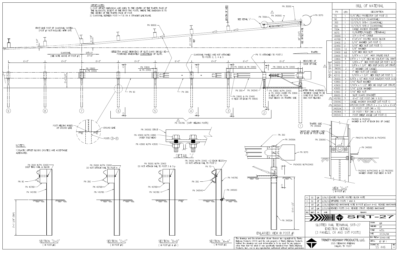
Version 05 is an all steel post version of SRT 350 03. It was approved in 2008 in letter cc-101. It's manual is supplied by Trinity Highway Industries, and the pdf is here.
- Head
- A shorter head (7.5"), forming roughly a U-shape at the end of the post
- Same head as the previous SRT
- Posts
- An all steel terminal (except for the offset blocks).
- Standard 6x8 inch routed wood terminal blockout or other FHWA-Accepted alternative blockouts used at posts 3 through 6.
- Steel Yielding Terminal Posts (SYTP) are used at posts 2 through 6.
- A steel Cable Release Post is used at post 1.
- Rail
- A 3.81m (12.5') slotted w-beam spanning posts 1 - 3
- Two 685mm (27") long slots
- Slots fall between post 1 - 2 and post 2 - 3
- A 3.81m (12.5') slotted w-beam spanning posts 3 - 5
- Two 300mm (12") slots, 2.655m (104.5") apart
- Slots fall between posts 3 - 4 and posts 4 - 5
- A 3.81m (12.5') unslotted w-beam spanning posts 6 - 9
- A 3.81m (12.5') slotted w-beam spanning posts 1 - 3
- Parts
- A shelf angle at post 2 provides rail support.
- Contains 4 trapezoidal folded steel slotguards with 6 bolts each at the downstream end of each of the slots
- A flange protector (short bit of w-beam) on post 2, but rail is not connected
- A rectangular slotted bearing plate - open end goes up
- Single 3"x3"xl/4" angle ground strut between post 1 and 2
- Post spacing
- Posts 1 - 7 spaced 6'3" (75") apart
- Post 7 is the first line post
- Flare
- The terminal is 37.5 feet long with a straight flare and a 4 foot end offset.
- Rail placement & attachment
- The rail is detached from the support posts 2 through 5.
¶ SRT_350_06 - Linear, wood, 31" high with 6 posts
Version 06 is a wood post version of the 31" high SRT. It was approved in 2014 in letter cc-100c.
[insert drawing]
- Flare
- Straight flare with 4-ft end offset over the 37.5-ft terminal length (similar to SRT-27WP, SRT-27SP, and SRT-31)
- Posts
- Wood BCT posts in 6 foot soil tubes or 4 ft-6 inch soil tubes with soil plates at post locations 1 and 2
- Cable Release Post (CRP) at post location 1 and 6-ft long Steel Yielding Terminal Post (SYTP) at post location 2 (similar to SRT-27SP and SRT-31 ).
- Four (4) 6-ft long Controlled Release Terminal (CRT) Posts connected to rail at post locations 3 through 6 with post spacing of 6 ft-3 inches (similar to SRT-27WP).
- No blockouts between rail and post at post locations 1 and 2 (similar to SRT-27WP, SRT-27SP, and SRT-31 ).
- 8 inch or 12 inch wood or composite blockout at post locations 3 through 6
- Standard line post at post location 7 and beyond (similar to SRT-27WP, SRT-27SP, and SRT-31 ).
- Rail
- Two 12.5 ft (3.8 m) slotted W-beam panels between posts 1 and 5 (similar to SRT-27WP, SRT-27SP, and SRT-31 )
- Special 9.375 ft (2.86 m) or 15.625 ft (4.76 m) long W-beam panel beginning at post 5 to provide mid-span rail splices for connected 31-inch guardrail system (similar to SRT-31 ).
- Parts
- Shelf angle is used at post location 2 (similar to SRT-27SP and SRT-31 )
- Post spacing
- Posts 1 - 7 spaced 6'3" (75") apart
- Post 7 is the first line post
¶ SRT_MASH_01
cc-100b
¶ SRT_MASH_02
cc-140
