¶ Extruder Terminal 2000 and 2000 Plus (ET-2000 / ET-2000 Plus)
¶ Overview
The Extruder Terminal 2000 and 2000 Plus (ET-2000/ET-2000 Plus) is a cable anchored, energy absorbing guardrail end treatment that may be used on the termination of W-Beam barriers on the shoulder or median of a roadway. It is tested to NCHRP Report 350 Test Level 2 and Test Level 3.
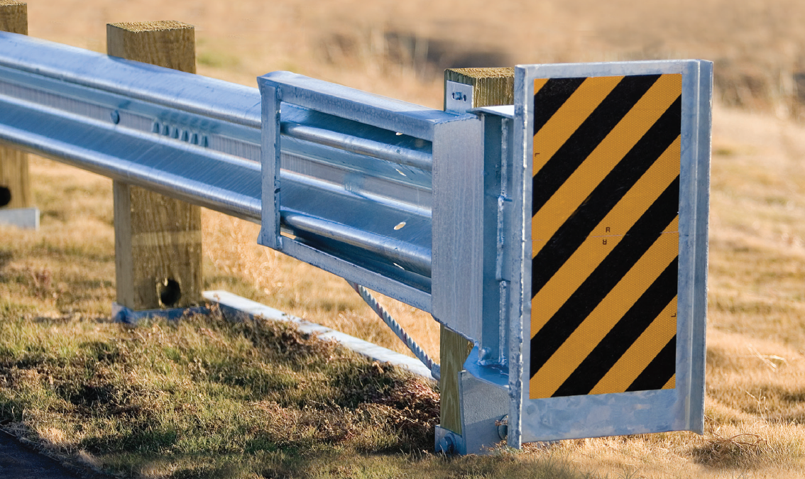
The design is currently owned and maintained by Trinity Highway Products LLC. It was originally designed by the Texas Transportation Institute (Texas A&M), to comply with the NCHRP 230 (National Cooperative Highway Research Project) standard. It was later updated to comply with NCHRP 350, which is when federal approval letters began being issued. This is when our guide picks up.
¶ Operation
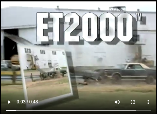
This video, though older, describes the operation of the ET-2000 well. Note that it does show an older version with rounded posts which are not approved for NCHRP 350 TL-3 use. It was sourced from Youtube.
Heads up, the video has sound 🔊.
¶ Common Issues
- Damage
- Tipped Head - Due to a missing fastener holding the head to post #1
- Inverted Bearing Plate
¶ Versions
The majority of the design variations involve variations in the post type and rail lengths used in this design. These have been broken into different versions for ease of identification, possible substitutions have been noted where possible.
¶ ETP 350 01 - The Original ET-2000 "Option A"
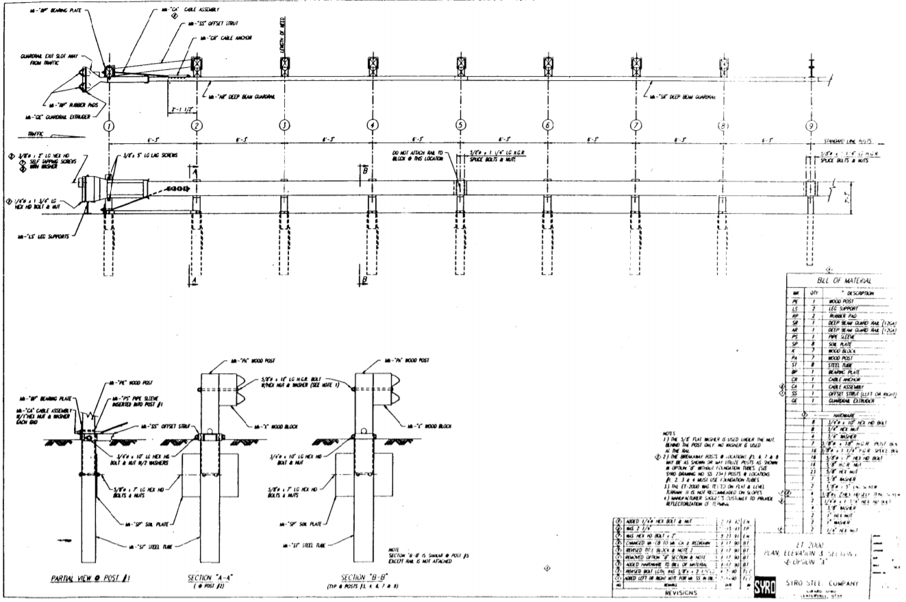
The first 350 approaved ETPlus design needed little legs to hold up the head.
¶ Identifying features
- It has little legs!!
- All wooden posts with no holes in them.
¶ Drawing
¶ Detailed Description
The first version of this design was approved in letter CC-12C.
- Head
- A square steel head with rubber bumpers or the rectangular ET-PLUS head as described in letter CC-12G
- Two leg supports under the upstream edge of the head if it is square
- Secured to post 1 with two lag screws thru a bracket above and below the head
- One side of the head is smooth while the other side has an obvious extruder slot
- The extruder slot must face away from traffic
- There may be a serial number on the head as specified in letter CC-12T
- Bearing Plate
- Large rectangular bearing plate with an off center whole (long side is ~ 5" and short side is ~ 3")
- Long end must be pointing up (basically defying gravity)
- Anchor Cable
- Short cable running from the base of post 1 up to the cable anchor bracket
- This must be tight
- Cable Anchor Bracket
- Steel block with 6 hooks visible thru the traffic face of the guardrail
- Sits between posts 1 and 2, close to post 2
- Ground Strut
- Steel ground strut between posts 1 and 2
- Must be sitting on grade
- Either a steel channel strut or a solid steel bar as described in letter CC-12I is acceptable
- Posts
- Shortened wooden posts in steel tubes (these should have no holes in them)
- 8 special posts with post 9 being a regular line post
- Under the ground there are soil plates
- Posts 1, 2, 3 and 4 must use foundation tubes
- Posts 5, 6, 7, and 8 may use CRT posts without foundation tubes as shown in ETP 350 02
- Some or all of these posts may be substituted with steel HBA posts described in ETP 350 04 given the loose wording in letter CC-12F if installed before July 2002.
- In June 2002 letter CC-12J specifically prohibited the mixing of posts.
- These can be replaced with a CRP and STYPs as described in ETP 350 06 as per letter CC-12J.
- From November 2005 damaged CRT posts in existing steel tubes may be replaced with SYTP posts (described in ETP 350 06) as per letter CC-12P.
- Blocks
- Wooden blocks on posts 2 - 8
- No block on post 1
- This means that the ground strut is angled away from the road
- Rail
- Two 25' sections of normal w beam
- Splices fall on post 5 and post 9
- Can also be used with two 12.5' panels in place of the 25' panels as approved in letter CC-12E
- This causes splices to fall on post 3, post 5, post 7 and post 9
- Bolts
- No bolt in post 1, just the lag screws holding the head on
- Not attached to post 5
- No washers may be used on the rail
- Post spacing
- All posts are 6' 3" apart
- Height
- The finished rail height must be ~ 27 5/8" high
¶ ETP 350 02 - The Original ET-2000 "Option B"
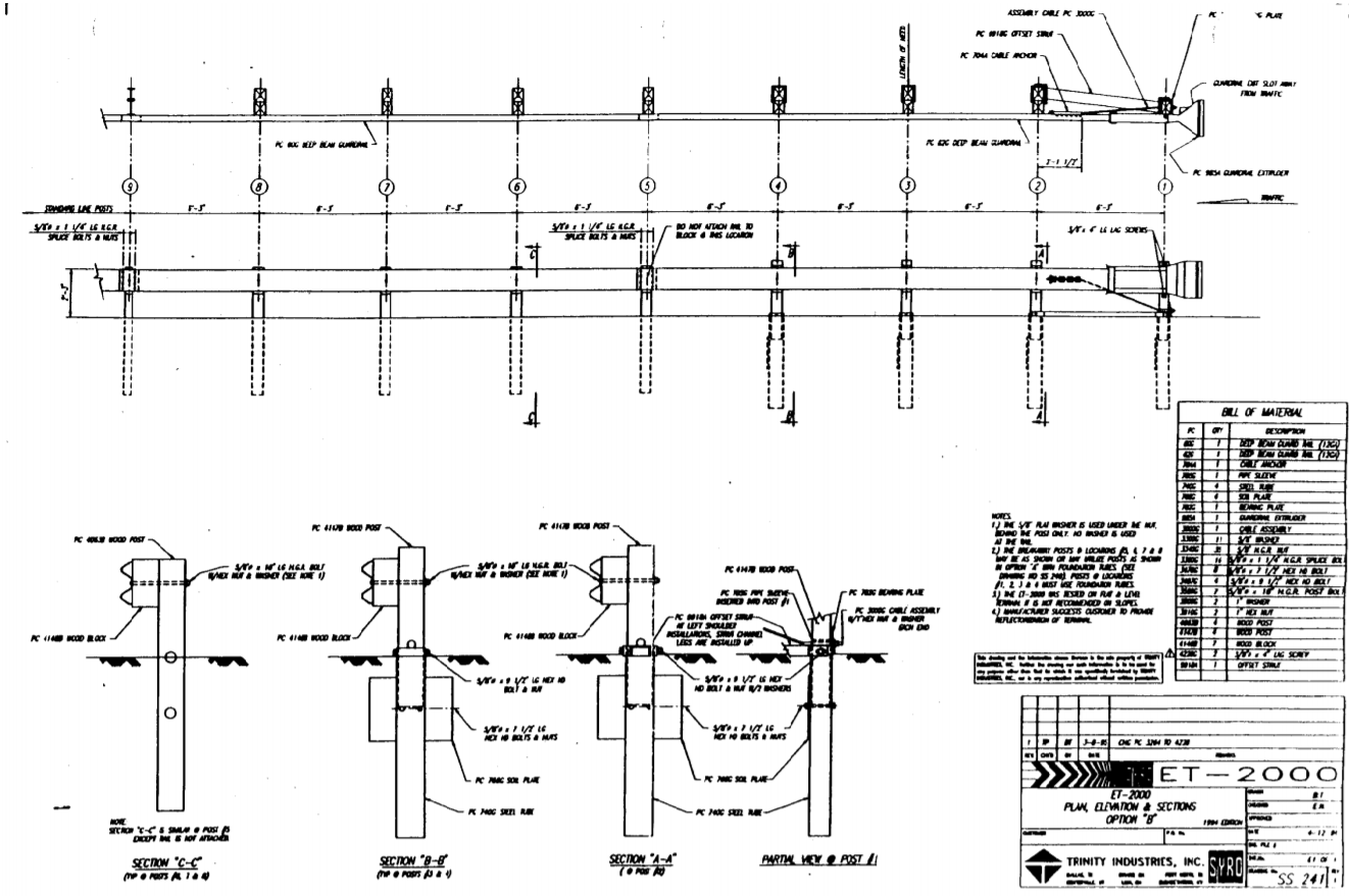
The second design incoporated Controlled Release Terminal (CRT) Posts. It looks more like the ETPlus we know today.
¶ Identifying features
- 8 wooden CRT posts (these posts have holes in them at or just above grade)
¶ Drawing
¶ Detailed Description
- Head
- A square steel head with rubber bumpers or the rectangular ET-PLUS head as described in letter CC-12G
- Secured to post 1 with two lag screws thru a bracket above and below the head
- One side of the head is smooth while the other side has an obvious extruder slot
- The extruder slot must face away from traffic
- There may be a serial number on the head as specified in letter CC-12T
- Bearing Plate
- Large rectangular bearing plate with an off center whole (long side is ~ 5" and short side is ~ 3")
- Long end must be pointing up (basically defying gravity)
- Anchor Cable
- Short cable running from the base of post 1 up to the cable anchor bracket
- This must be tight
- Cable Anchor Bracket
- Steel block with 6 hooks visible thru the traffic face of the guardrail
- Sits between posts 1 and 2, close to post 2
- Ground Strut
- Steel ground strut between posts 1 and 2
- Must be sitting on grade
- Either a steel channel strut or a solid steel bar as described in letter CC-12I is acceptable
- Posts
- Shortened CRT posts in steel foundation tubes (these posts have a large circular hole in them just above grade) for posts 1 - 4
- Full length CRT posts without or without soil tubes for posts 5 - 8
- Soil plates under ground at posts 1 - 4
- Posts 1, 2, 3 and 4 must use foundation tubes and CRT posts
- Posts 5, 6, 7, and 8 may use normal posts with soil tubes as per ETP 350 01
- Some or all of these posts may be substituted with steel HBA posts described in ETP 350 04 given the loose wording in letter CC-12F if installed before July 2002.
- In June 2002 letter CC-12J specifically prohibited the mixing of posts.
- These can be also be replaced with a CRP and STYPs as described in ETP 350 06 as per letter CC-12J.
- From November 2005 damaged CRT posts in existing steel tubes may be replaced with SYTP posts (described in ETP 350 06) as per letter CC-12P.
- Blocks
- Wooden blocks on posts 2 - 8
- No block on post 1
- This means that the ground strut is angled away from the road
- Rail
- Two 25' sections of normal w beam
- Splices fall on post 5 and post 9
- Can also be used with two 12.5' panels in place of the 25' panels as approved in letter CC-12E
- This causes splices to fall on post 3, post 5, post 7 and post 9
- Bolts
- No bolt in post 1, just the lag screws holding the head on
- Not attached to post 5
- No washers may be used on the rail
- Post spacing
- All posts are 6' 3" apart
- Height
- The finished rail height must be ~ 27 5/8" high
¶ ETP 350 03 - The LET
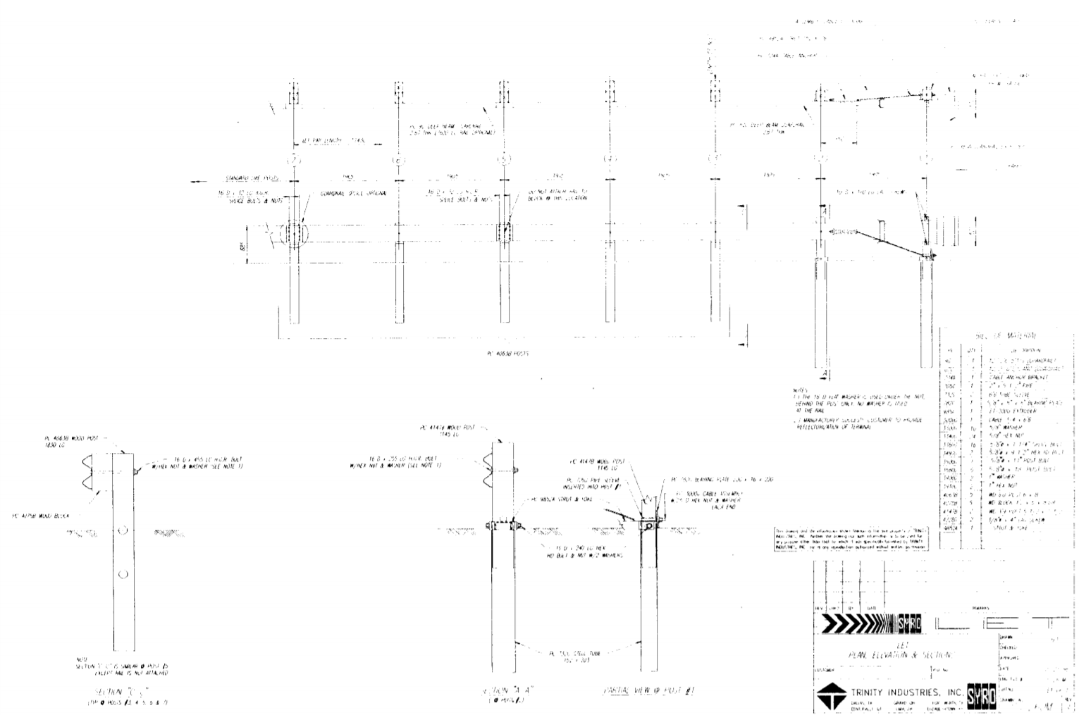
This design was approved in letter CC-12D.
¶ Identifying features
- No blocks behind posts 1 and 2
- 7 wooden CRT posts
¶ Drawing
¶ Detailed Description
- Head
- A square steel head or the rectangular ET-PLUS head as described in letter CC-12G
- Secured to post 1 with two lag screws thru a bracket above and below the head
- One side of the head is smooth while the other side has an obvious extruder slot
- The extruder slot must face away from traffic
- There may be a serial number on the head as specified in letter CC-12T
- Bearing Plate
- Large rectangular bearing plate with an off center whole (long side is ~ 5" and short side is ~ 3")
- Long end must be pointing up (basically defying gravity)
- Anchor Cable
- Short cable running from the base of post 1 up to the cable anchor bracket
- This must be tight
- Cable Anchor Bracket
- Steel block with 6 hooks visible thru the traffic face of the guardrail
- Sits between posts 1 and 2, close to post 2
- Ground Strut
- Steel ground strut between posts 1 and 2
- Must be sitting on grade
- Either a steel channel strut or a solid steel bar as described in letter CC-12I is acceptable
- Posts
- Shortened CRT posts in soil tubes for post 1 and 2
- Full length CRT posts without soil tubes for posts 3 - 7
- Normal line posts start at post 8
- No soil posts
- Posts 1, 2, 3 and 4 must use foundation tubes and CRT posts
- Posts 5, 6, 7, and 8 may use normal posts with soil tubes as per ETP 350 01
- Some or all of these posts may be substituted with steel HBA posts described in ETP 350 04 given the loose wording in letter CC-12F if installed before July 2002. In June 2002 letter CC-12J specifically prohibited the mixing of posts.
- These can be replaced with a CRP and STYPs as described in ETP 350 06 as per letter CC-12J.
- From November 2005 damaged CRT posts in existing steel tubes may be replaced with SYTP posts (described in ETP 350 06) as per letter CC-12P.
- Blocks
- Wooden blocks on posts 3 - 7
- No block on post 1 and 2
- This means that the ground strut is tangent to the road
- Rail
- One 25' section of normal w beam spanning posts 1 - 5
- One 12.5' section of normal w beam spanning posts 5 - 7
- Splices fall on post 5 and post 7
- Can also be used with two 12.5' panels in place of the 25' panels as approved in letter CC-12E
- This causes splices to fall on post 3, post 5, post 7 and post 9
- Bolts
- No bolt in post 1, just the lag screws holding the head on
- Not attached to post 5
- No washers may be used on the rail
- Post spacing
- All posts are 6' 3" apart
- Height
- The finished rail height must be ~ 27 5/8" high
¶ ETP 350 04 - ET-2000 Steel HBA posts
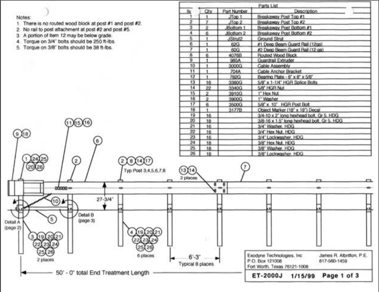
This design incorporates steel Hinged Breakaway Posts (HBA). The letter certified these new posts for use with previous versions of the system.
This design was approved in letter CC-12F.
¶ Identifying features
- 8 steel HBA posts
¶ Drawing
¶ Detailed Description
- Head
- A square steel head or the rectangular ET-PLUS head as described in letter CC-12G
- Secured to post 1 with two lag screws thru a bracket above and below the head
- One side of the head is smooth while the other side has an obvious extruder slot
- The extruder slot must face away from traffic
- There may be a serial number on the head as specified in letter CC-12T
- Bearing Plate
- Large rectangular bearing plate with an off center whole (long side is ~ 5" and short side is ~ 3")
- Long end must be pointing up (basically defying gravity)
- Anchor Cable
- Short cable running from the base of post 1 up to the cable anchor bracket
- This must be tight
- Cable Anchor Bracket
- Steel block with 6 hooks visible thru the traffic face of the guardrail
- Sits between posts 1 and 2, close to post 2
- Ground Strut
- Steel ground strut between posts 1 and 2
- Must be sitting on grade
- Posts
- Steel HBA (hinged break away) posts for posts 1 - 8
- These posts have two bolts at or slightly above grade. The lower, upstream bolt is smaller that the downstream bolt. When hit the smaller bolt shears and the larger bolt acts as a pivot
- Be sure to check the bolting and orientation of these posts
- Post 1 and 2 are slightly different in order to accommodate the ground strut assembly
- Some of these posts may be substituted with wooden CRT posts given the loose wording in letter CC-12F if installed before July 2002. In June 2002 letter CC-12J specifically prohibited the mixing of posts.
- These can be completely replaced with a CRP and STYPs as described in ETP 350 06 as per letter CC-12J.
- Blocks
- Wooden blocks on posts 3 - 7
- No block on post 1 and 2
- This means that the ground strut is tangent to the road
- Rail
- Two 25' sections of normal w beam
- Splices fall on post 5 and post 9
- This is as per the drawing in letter CC-12F. 12.5' sections are also permissible.
- Bolts
- No bolt in post 1, just the lag screws holding the head on
- Not attached to post 2 or post 5 (this is unclear for mixed systems given that the CRT version does attach at post 2, but HBA version does not)
- No washers may be used on the rail
- Post spacing
- All posts are 6' 3" apart
- Height
- The finished rail height must be ~ 27 5/8" high
¶ ETP 350 05 - TL-2 System
This is a modified version of the ET-PLUS for use in lower speed zones (at or under 45mph). This is know as test level 2 (TL-2).
This design was approved in letter CC-12H.
¶ Identifying features
- 6 steel HBA or CRT posts
¶ Drawing
¶ Detailed Description
- Head
- A square steel head or the rectangular ET-PLUS head as described in letter CC-12G
- Secured to post 1 with two lag screws thru a bracket above and below the head
- One side of the head is smooth while the other side has an obvious extruder slot
- The extruder slot must face away from traffic
- There may be a serial number on the head as specified in letter CC-12T
- Bearing Plate
- Large rectangular bearing plate with an off center whole (long side is ~ 5" and short side is ~ 3")
- Long end must be pointing up (basically defying gravity)
- Anchor Cable
- Short cable running from the base of post 1 up to the cable anchor bracket
- This must be tight
- Cable Anchor Bracket
- Steel block with 6 hooks visible thru the traffic face of the guardrail
- Sits between posts 1 and 2, close to post 2
- Ground Strut
- Steel ground strut between posts 1 and 2
- Must be sitting on grade
- Posts
- Steel HBA (hinged break away) for posts 1 - 6
- These posts have two bolts at or slightly above grade. The lower, upstream bolt is smaller that the downstream bolt. When hit the smaller bolt shears and the larger bolt acts as a pivot
- Be sure to check the bolting and orientation of these posts
- Post 1 and 2 are slightly different in order to accommodate the ground strut assembly
- Some of these posts may be substituted with wooden CRT posts given the loose wording in letter CC-12F if installed before July 2002. In June 2002 letter CC-12J specifically prohibited the mixing of posts.
- These can be replaced with a CRP and STYPs as described in ETP 350 06 as per letter CC-12J and letter CC-12M
- Blocks
- Wooden blocks on posts 3 - 7
- No block on post 1 and 2
- This means that the ground strut is tangent to the road
- Rail
- Two 25' sections of normal w beam
- Splices fall on post 5 and post 9
- This is as per the drawing in letter CC-12F. 12.5' sections also appear to be permissible.
- Bolts
- No bolt in post 1, just the lag screws holding the head on
- No washers may be used on the rail
- Post spacing
- All posts are 6' 3" apart
- Height
- The finished rail height must be ~ 27 5/8" high
¶ ETP 350 06 - CRP and SYTPs
This design incorporates two different post designs, the Controlled Release Post (CRP) and the Steel Yielding Terminal Post (SYTP). The letter granted the use of these posts in previous systems (to an extent).
This design was approved in letter cc-12j.
¶ Identifying features
- 1 steel post 1 with bolts and 7 steel posts with holes in them (SYTPs of two different thicknesses).
¶ Drawing
¶ Detailed Description
- Head
- A square steel head or the rectangular ET-PLUS head as described in letter CC-12G
- Secured to post 1 with two lag screws thru a bracket above and below the head
- There may be a serial number on the head as specified in letter CC-12T
- One side of the head is smooth while the other side has an obvious extruder slot
- The extruder slot must face away from traffic
- Bearing Plate
- Large rectangular bearing plate with an off center whole (long side is ~ 5" and short side is ~ 3")
- Long end must be pointing up (basically defying gravity)
- Anchor Cable
- Short cable running from the base of post 1 up to the cable anchor bracket
- This must be tight
- Cable Anchor Bracket
- Steel block with 6 hooks visible thru the traffic face of the guardrail
- Sits between posts 1 and 2, close to post 2
- Ground Strut
- Steel ground strut between posts 1 and 2
- Must be sitting on grade
- Posts
- Post 1 is a cable release post (CRP) which is composed of two sections similar to an HBA post 1. It may be subsituted for a HBA post as per letter CC-12k. It may also be a slightly modified version described in letter CC-12N
- Post 2 - 8 are steel yeilding terminal posts (SYTPs) which are single piece W200 x 15 hot rolled steel sections ~ 6' long with two holes drilled in the flange at the ground line. These may also be made using a smaller post with similar holes as per letter CC-12L
- This post configuration was also approved for all previous versions of the ET, though the ability to mix and match posts was specifically revoked in letter CC-12J which appear in 2002.
- Blocks
- Wooden blocks on posts 3 - 7
- No block on post 1 and 2
- This means that the ground strut is tangent to the road
- Rail
- Two 25' sections of normal w beam
- Splices fall on post 5 and post 9
- This is as per the drawing in letter CC-12F. 12.5' sections also appear to be permissible.
- Bolts
- No bolt in post 1, just the lag screws holding the head on
- No washers may be used on the rail
- Post spacing
- All posts are 6' 3" apart
- Height
- The finished rail height must be ~ 27 5/8" high
¶ ETP 350 07 - ET-Plus 31
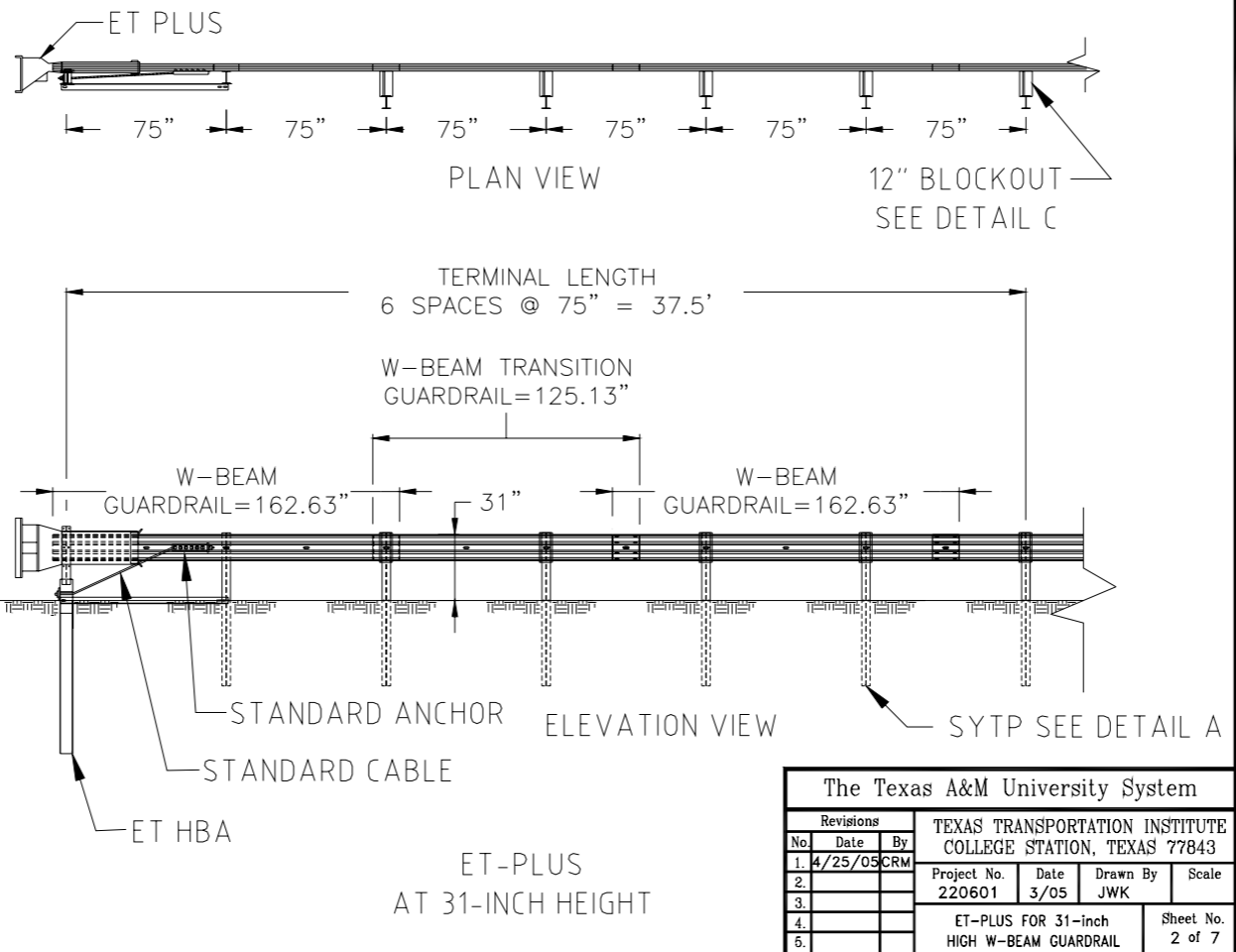
This new ET-Plus is designed for the 31" high Midwest Guardrail System and the Trinity Guardrail System. Previous systems were about 27" high.
This design was approved in letter CC-94.
¶ Identifying features
- 31 inches high with a splice between posts 4 and 5.
¶ Drawing
¶ Detailed Description
- Head
- A rectangular ET-PLUS head as described in letter CC-12G
- There may be a serial number on the head as specified in letter CC-12T
- Secured to post 1 with two lag screws thru a bracket above and below the head
- One side of the head is smooth while the other side has an obvious extruder slot
- The extruder slot must face away from traffic
- Bearing Plate
- Large rectangular bearing plate with an off center whole (long side is ~ 5" and short side is ~ 3")
- Long end must be pointing up (basically defying gravity)
- Anchor Cable
- Short cable running from the base of post 1 up to the cable anchor bracket
- This must be tight
- Cable Anchor Bracket
- Steel block with 6 hooks visible thru the traffic face of the guardrail
- Sits between posts 1 and 2, close to post 2
- Ground Strut
- Steel ground strut between posts 1 and 2
- Must be sitting on grade
- Posts
- Post 1 is a modified hinged breakaway (HBA) post which is composed of two sections bolted together.
- Post 2 - 6 are modified steel yeilding terminal posts (SYTPs) which are single piece W200 x 15 hot rolled steel sections ~ 6' long with two holes drilled in the flange at the ground line.
- Post 2 - 6 may also be replaced with standard line wood posts as per letter CC-94a
- Post 7 on are standard line posts.
- Blocks
- Slightly larger spacer blocks 12" from post 3 on
- No block on post 1 and 2
- This means that the ground strut is tangent to the road
- Rail
- A 12.5' section from post 1 to post 3.
- A special 9.375' section which places the splice between posts 4 and 5, in accordance with the Midwest Guardrail System.
- Bolts
- No bolt in post 1, just the lag screws holding the head on
- No washers may be used on the rail
- Normal bolting in all other posts
- Post spacing
- All posts are 6' 3" apart
- Height
- The finished rail height must be ~ 31" high
¶ ETP 350 08 - ET-Plus 31 w/ two posts
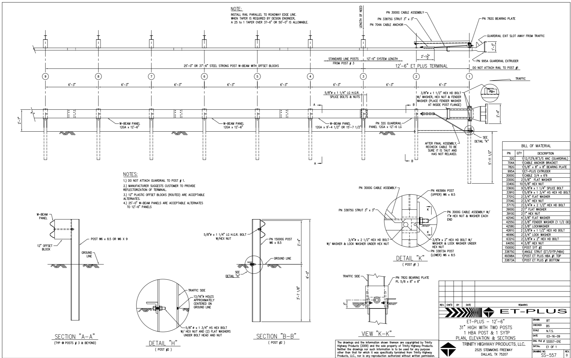
This design reduced the number of special break-away posts required to two.
This design was approved in letter CC-12Q.
¶ Identifying features
- 31 inches high with a splice between posts 4 and 5
- Only 2 posts before the normal line posts start
¶ Drawing
¶ Detailed Description
- Head
- A rectangular ET-PLUS head as described in letter CC-12G
- Secured to post 1 with two lag screws thru a bracket above and below the head
- One side of the head is smooth while the other side has an obvious extruder slot
- There may be a serial number on the head as specified in letter CC-12T
- The extruder slot must face away from traffic
- Bearing Plate
- Large rectangular bearing plate with an off center whole (long side is ~ 5" and short side is ~ 3")
- Long end must be pointing up (basically defying gravity)
- Anchor Cable
- Short cable running from the base of post 1 up to the cable anchor bracket
- This must be tight
- Cable Anchor Bracket
- Steel block with 6 hooks visible thru the traffic face of the guardrail
- Sits between posts 1 and 2, close to post 2
- Ground Strut
- Steel ground strut between posts 1 and 2
- Must be sitting on grade
- Posts
- Post 1 is a modified hinged breakaway (HBA) post which is composed of two sections bolted together.
- Post 2 is a modified steel yeilding terminal posts (SYTPs) which are single piece W200 x 15 hot rolled steel sections ~ 6' long with two holes drilled in the flange at the ground line.
- Post 3 on are standard line posts.
- Blocks
- Slightly larger spacer blocks 12" from post 3 on
- No block on post 1 and 2
- This means that the ground strut is tangent to the road
- Rail
- A 12.5' section from post 1 to post 3.
- A special 9.375' section which places the splice between posts 4 and 5, in accordance with the Midwest Guardrail System.
- Bolts
- No bolt in post 1, just the lag screws holding the head on
- No washers may be used on the rail
- Normal bolting in all other posts
- Post spacing
- All posts are 6' 3" apart
- Height
- The finished rail height must be ~ 31" high
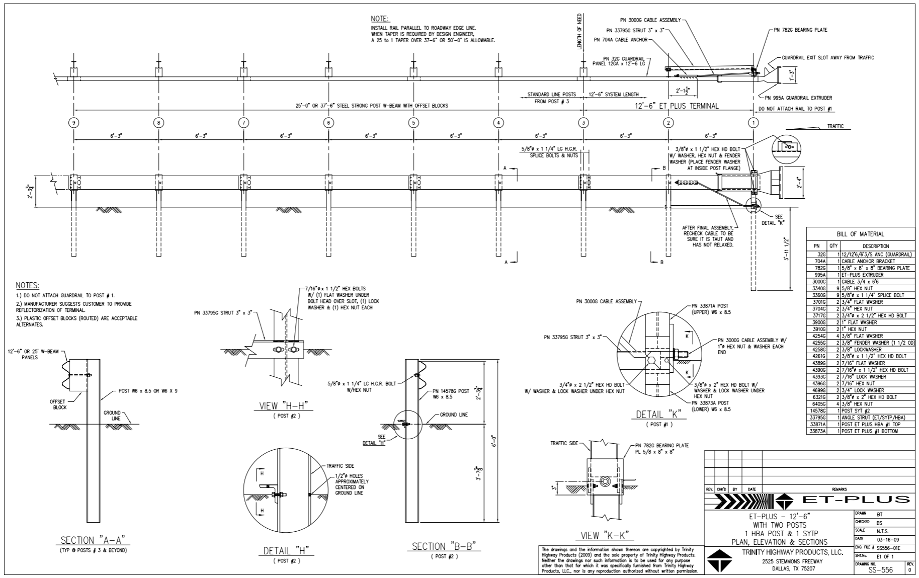
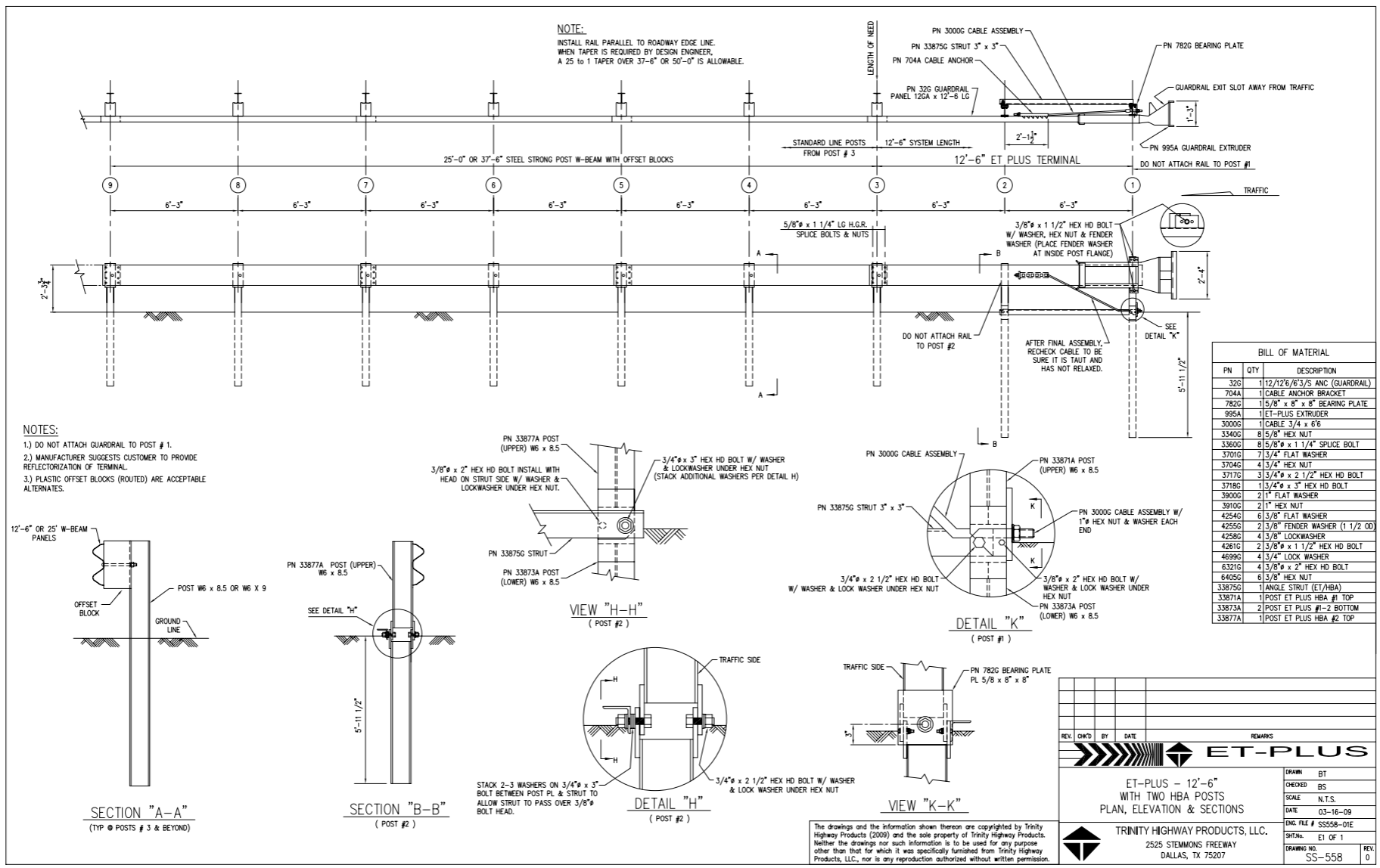
¶ ETP 350 09 - ET-Plus w/ two steel posts
The final updated to the ET-Plus design was to allow different types of post to be used in the two post system.
This design was approved in letter CC-12Q.
¶ Identifying features
- 31 inches high with a splice between posts 4 and 5
- Only 2 posts before the normal line posts start
- Metal posts instead of CRTs
¶ Drawing
¶ Detailed Description
- Head
- A rectangular ET-PLUS head as described in letter CC-12G
- Secured to post 1 with two lag screws thru a bracket above and below the head
- One side of the head is smooth while the other side has an obvious extruder slot
- The extruder slot must face away from traffic
- There may be a serial number on the head as specified in letter CC-12T
- Bearing Plate
- Large rectangular bearing plate with an off center whole (long side is ~ 5" and short side is ~ 3")
- Long end must be pointing up (basically defying gravity)
- Anchor Cable
- Short cable running from the base of post 1 up to the cable anchor bracket
- This must be tight
- Cable Anchor Bracket
- Steel block with 6 hooks visible thru the traffic face of the guardrail
- Sits between posts 1 and 2, close to post 2
- Ground Strut
- Steel ground strut between posts 1 and 2
- Must be sitting on grade
- Posts
- Post 1 is a hinged breakaway (HBA) post which is composed of two sections bolted together.
- Post 2 is a steel yielding terminal posts (SYTPs) which are single piece W200 x 15 hot rolled steel sections ~ 6' long with two holes drilled in the flange at the ground line.
- Post 2 may also be another HBA post identifiable by the bolt at ground level on the traffic side in the second post.
- Post 3 on are standard line posts.
- Blocks
- Spacer blocks from post 3 on
- No block on post 1 and 2
- This means that the ground strut is tangent to the road
- Rail
- A 12.5' section from post 1 to post 3.
- Bolts
-
No bolt in post 1, just the lag screws holding the head on
-
No washers may be used on the rail
-
Normal bolting in all other posts
-
If a HBA posts is used for post 2 then post two should not be connected to the rail
-
- Post spacing
- All posts are 6' 3" apart
- Height
- The finished rail height must be ~ 27 5/8" high
